
This topic has been archived, and won't accept reply postings.
 Hype or awesome? Are these Totem Cams going to fall to bits or hold your fall?
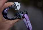
We sent Rob Greenwood hurtling through the air to find out if the Totem Cams were as good as some people say. He survived to bring you this review...
"The UKC Gear Testing budget doesn't extent to flights to America, so on this occasion I had to favour Millstone instead of El Capitan..."
Read more at http://www.ukclimbing.com/gear/review.php?id=6994
2
7
14
In reply to PPP:
CMK have had their store robbed and loads of inventory taken recently - so I try and help 'em out
CMK have had their store robbed and loads of inventory taken recently - so I try and help 'em out
1
In reply to simes303:
I think you could be overlooking the unique features of Totem cams...?
> Sixty Eight quid is really taking the piss for one cam.
I think you could be overlooking the unique features of Totem cams...?
5
In reply to simes303:
You must be apolplectic with rage seeing the price of a Camalot 6!
http://www.outside.co.uk/shop/Camalot+C4?utm_source=google&utm_medium=s...
If you don't want to spend £68 on arguably the best cam on the market (more likely to fit in a placement, most likely to hold a fall), don't.
You must be apolplectic with rage seeing the price of a Camalot 6!
http://www.outside.co.uk/shop/Camalot+C4?utm_source=google&utm_medium=s...
If you don't want to spend £68 on arguably the best cam on the market (more likely to fit in a placement, most likely to hold a fall), don't.
In reply to planetmarshall:
Hope someone gets some of these stuck and posts on here asking for some nice chap to pop along ,get them out and post them back ,it'll be a popular crag the day after
Hope someone gets some of these stuck and posts on here asking for some nice chap to pop along ,get them out and post them back ,it'll be a popular crag the day after
2
In reply to UKC Gear:
Anyone got an idea at which range do they shine the best? You can get 3 Dragons for price of 2 Totems, but I wouldn't mind trying them once I feel a little bit richer.
I currently have Wallnuts, Alloy+Brass Offsets, Torques and Dragons in sizes 00 to 3 (1 each).
Anyone got an idea at which range do they shine the best? You can get 3 Dragons for price of 2 Totems, but I wouldn't mind trying them once I feel a little bit richer.
I currently have Wallnuts, Alloy+Brass Offsets, Torques and Dragons in sizes 00 to 3 (1 each).
In reply to PPP:
I bought a full set a couple of years ago to replace my 1980s vintage Friends. Green and Purple are the sizes I most often find myself wishing I had doubles of.
I bought a full set a couple of years ago to replace my 1980s vintage Friends. Green and Purple are the sizes I most often find myself wishing I had doubles of.
1
In reply to UKC Gear:
I bought a couple a few years ago when they first came out. They were on a par with any other cam price wise back then. I can only assume the increase in popularity has caused the price to jump.
I bought a couple a few years ago when they first came out. They were on a par with any other cam price wise back then. I can only assume the increase in popularity has caused the price to jump.
1
In reply to Wsdconst:
The problem with that is the review says they are more difficult than other cams to get stuck.
> Hope someone gets some of these stuck and posts on here asking for some nice chap to pop along ,get them out and post them back ,it'll be a popular crag the day after
The problem with that is the review says they are more difficult than other cams to get stuck.
1
In reply to DubyaJamesDubya:
I'm sure a complete incompetent could still get them to stick. Even if they don't walk very much at all you could still probably find some sort of inappropriate placement to get it stuck in.
I'm sure a complete incompetent could still get them to stick. Even if they don't walk very much at all you could still probably find some sort of inappropriate placement to get it stuck in.
In reply to DubyaJamesDubya:
More difficult yes ,impossible no.all you need is a late start,a nervous leader,a newbie seconder,a sudden change of weather infact you can mix and match any of these to result in a stuck cam,have a go yourself but remember to post on here asking for it back
> The problem with that is the review says they are more difficult than other cams to get stuck.
More difficult yes ,impossible no.all you need is a late start,a nervous leader,a newbie seconder,a sudden change of weather infact you can mix and match any of these to result in a stuck cam,have a go yourself but remember to post on here asking for it back
1
In reply to UKC Gear:
Curious about the statement that these cams will exert a greater force on the placement than other cams - surely the downward force must be entirely redirected outwardly in all instances? I can see that the angle the force is applies may differ but I would like this claim explained.. If more energy is coming out of the cams than going in then the value of the device will transcend climbing...
Curious about the statement that these cams will exert a greater force on the placement than other cams - surely the downward force must be entirely redirected outwardly in all instances? I can see that the angle the force is applies may differ but I would like this claim explained.. If more energy is coming out of the cams than going in then the value of the device will transcend climbing...
In reply to Adrian Berry:
The force exerted is a function of camming angle. Bit like a length of a lever analogy: the longer the lever, the higher the force. Similarly the greater the camming angle the greater the force.
The force exerted is a function of camming angle. Bit like a length of a lever analogy: the longer the lever, the higher the force. Similarly the greater the camming angle the greater the force.
In reply to GrahamD:
Not quite. A small camming angle will exert a higher force. Think about a triangle of forces. You have a vector of force running effectively along the length of the cam. You have a vector of force acting perpendicular to the rock face, and you have a vector of force running between the point of cam lobe/rock contact and the axle at the centre of the lobe. This always true, whatever the cam. The larger the angle between the load vector and the cam/rock interface vector is, the higher the resultant force exerted horizontally is. The angle between these is in a perfect world 90degs minus the camming angle, i.e. 12 degs camming angle produces a greater angle for the force to act over than 16 degs.
The greater force they are talking about has to do with coefficient of friction between the cam surface and the rock surface. The way the totem totems work is for the cam lobe to be actively rotated into the rock by the load exerted downwards. This active rotation effectively increases friction as you have a greater load pressing the two surfaces together and this is what makes them stick well. This is more a question of in the first instance of a fall, that the cam lobe stays put. In a normal cam, all that is providing this friction is the force exerted by the return spring and this remains the case whatever. In totems case, as soon as the load is applied, the cam is being actively pasted to the rock... hope that's understandable?
In reply to UKC Gear:
I think I understand the above replies, but would it not be more accurate to say that the camming angle determines the direction the force is applied (the vector), so that a (theoretical) 90deg camming angle would direct force 'horizontally' and a (theoretical) 0deg camming angle would direct force entirely downwards.
I think I understand the above replies, but would it not be more accurate to say that the camming angle determines the direction the force is applied (the vector), so that a (theoretical) 90deg camming angle would direct force 'horizontally' and a (theoretical) 0deg camming angle would direct force entirely downwards.
In reply to Adrian Berry:
0 deg camming angle would mean the cam would be a circle, and the force applied to the rock wall would be at 90 degs to the load. Of course it wouldn't work though... On this diagram you've got sf which is the force vector from the cam contact spot to the axle. you've got H, the resultant horizontal force, i.e. the force exerted outwards on the rock, and you've got F, the vertical component of the load force pulling down on the lobe, usually 1/4 of the total load. The geometry of this grafically shows the size of the resultant forces - as alpha the angle between them all increases, if F stays the same, the H leg of the diagram gets shorter, i.e. the force gets smaller. http://www.bigwalls.net/climb/camf/Camfigs/Camf3.gif
This diagram is the more relevent one with respect to what we are talking about:
http://www.waveequation.com/surfboard_wax_friction_defs.gif
Basically take this diagram and turn it on it's side and stick it where the camlobe contact spot is. Which is why the H component is important. Instead of an object and mass, replace it with the cam lobe and a force pressing down on the surface. The frictional force (and therefore the pull out force required to make the cam fail) is the coefficient of friction (variable on surface roughnesses and granular structure of the material (but not surface area)) multiplied by the normal (i.e. perpendicular to the surface) force exerted by the cam lobe on the surface.
So if you increase the normal force, you get higher frictional force and higher pull out loadings are possible. This is entirely separate to the force exerted outwards during that loading of the walls by the cam lobes. All the Totem does is use a lever effect by virtue of where the load cables are attached to push the cam lobes into the rock more firmly and therefore increases the normal force.
The final component which is more of a real world issue is that of rock pulverisation. Generally the way a real world placement will fail is that the force pressing outwards on the rock ( the SF component) will make the rock fail, either by flexing the rock or moving it (behind a flake for example - like on the Sloth) or by pulverising the rock. The former you can do absolutely nothing about. The latter you can. Previously I mentioned surface area being independent of friction - which it is. However a materials strength is based on the stress it can withstand. Stress is a function of force and surface area - if the force remains constant, the stress induced in the material can be reduced by spreading that force over a larger area. I.e. make the cam lobe wider, and increase surface area and in theory you will see a reduced stress in the rock walls. This is important where stone is relatively soft e.g. sand stone as they tend to be able to withstand less stress. With a thin cam lobe, the stress is higher and the rock pulverises creating a layer of sand and dust between the rock and the cam lobe and this reduces the frictional force we were talking about before resulting in a pull out.
So, you have to blend several factors:
Cam material - a softer material deflects more and causes greater mechanical interferance between rock grain structure and the metal surface - it increases the coefficient of friction.
Cam angle (friction) - lower cam angle means higher normal force to provide greater friction.
Cam width - reduces induced stress in the rock surface which is particularly relevant in soft rock
Number of cams - 4 cams spread the load between 4 lobes, i.e. lower induced force in each contact spot - hence why 3 cam units have a wider middle lobe.
Cam angle (range) - the higher the cam angle, the tighter the exponential spiral which governs the cam surface becomes, and the result is a greater differential there is as the cam moves from fully open to fully closed - i.e. more range.
Cam angle (outward load) - the lower the cam angle, the greater the H component becomes andthe more likely you are to pulverise the rock or break a flake
Cam angle (lobe strength) - the lower the cam angle, the more stress is induced in the cam lobe. This is less of a problem with small cams, but a big problem with large cams when the cam lobe will simply buckle with higher force. hence a large cam lobe needs to be inherently stronger to cope with this stress.
Cam angle (loss of friction) - as you get to very high cam angles, the cam lobe lose friction - hence the magic 13.75 number. Jardine figured this was the best compromise before you start losing too much friction and the pull out force starts to drop dramatically.
Aliens use 16ish - they use a soft metal to increase friction - it's the only reason they stick well - 6061T6 is as soft as butter. If he had used 13.75 they would stick even better. But you can't use the material for large lobes as you compromise strength too much.
Camalots are in the region of 15 degs and use 6082 t6 (I think - that's from memory!) as it's much strongerbut still fairly soft. In addition 6000 series is easier to extrude. 15 allows them to fully maximise the range of the unit to reap th rewards of their double axle design.
DMM Dragons and WC cams use 13.75 and 6082 t6 - theoretically a higher holding power than BD. The dragons you will notice have a marginally smaller range than BD's, but we're talking a gnats chuff - that's the cam angle taking effect.
Metolius, last but not least use I believe 13.25 and 7075-t6. The material is super hard and durable, but less grippy as a consequence. 13.25 allows for friction to be increased again.
As for totem totems - don't know, for sure - but you get the drift?
6
In reply to chuffer:
The power of incompetence knows no bounds!
> I'm sure a complete incompetent could still get them to stick. Even if they don't walk very much at all you could still probably find some sort of inappropriate placement to get it stuck in.
The power of incompetence knows no bounds!
In reply to beardy mike:
Hmm, all cams 'actively rotate into the rock' which is the H component generated by any camming angle - unless you degenerate to a perfectly circular cam where the H component drops to zero. So the Totem cams have a relatively high camming angle which gives them a higher than average 'outward' (h) force vector but presumably at the cost of range.
Hmm, all cams 'actively rotate into the rock' which is the H component generated by any camming angle - unless you degenerate to a perfectly circular cam where the H component drops to zero. So the Totem cams have a relatively high camming angle which gives them a higher than average 'outward' (h) force vector but presumably at the cost of range.
In reply to beardy mike:
Exactly my thoughts the other day as I teetered on the edge of falling off and hurriedly placed a cam. By the time I'd processed all the information however and decided on the Totem over the Camalot it was too late and I was off
Exactly my thoughts the other day as I teetered on the edge of falling off and hurriedly placed a cam. By the time I'd processed all the information however and decided on the Totem over the Camalot it was too late and I was off
Post edited at 16:33
In reply to GrahamD:
Hi Graham, when I say actively rotate, what i mean is that the main load is being exerted onto the cam lobe pulling it round the axle and pushing the cam lobe actively into the rock, thus increasing H. In a normal cam, the only thing holding the cam in place during the beginning of the fall is the spring tension. If the friction is nor sufficient, the cam surface will slide over the surface of the rock. This is often the case with very smooth rocks like limestone, or where friction is decreased by virtue of the crack being flared for example. The totem cam, if it slides, the force being exerted by the fall load is actively pushing the cam lobe into place and increasing the friction, i.e. It effectively grabs.
And grid north, if you're carrying totems and camalots, you're carrying WAY too much gear
In reply to GrahamD:
Nope. Most cams pull on the axle via the stem. Totem cams are fundamentally different in that they pull on the cam itself and that is where the extra holding power comes from.
> Hmm, all cams 'actively rotate into the rock' which is the H component generated by any camming angle - unless you degenerate to a perfectly circular cam where the H component drops to zero. So the Totem cams have a relatively high camming angle which gives them a higher than average 'outward' (h) force vector but presumably at the cost of range.
Nope. Most cams pull on the axle via the stem. Totem cams are fundamentally different in that they pull on the cam itself and that is where the extra holding power comes from.
For those, like me, whose head starts to spin once the vector diagrams start coming out, I see it like this:
Put a totem and a normal cam next to each other.
With a normal cam the axle around which the cam rotates is connected to the stem. And you clip the rope to the base of the stem.
With a totem the axle is again connected to a stem, but you don't clip the stem. Take a look, the stem is only 2 inches long. You clip the wires embedded in the cams and hang off those. This gives the impression of a lever as the wires exit from the back of the cam. However, I have no idea if this does give more grip at the start of the fall. The 'lever' is also of differing length depending on how compressed the cam is.
Post edited at 10:49
In reply to IainWhitehouse:
I'm still struggling with this one. I can't see where the horizontal force multiplier comes from. As far as I can see the only thing that matters in resolving the H force vector is the angle made by the floating axle and the point of contact on the rock irrespective of where the vertical force is being applied. I'd like to see the diagram showing otherwise !
I'm still struggling with this one. I can't see where the horizontal force multiplier comes from. As far as I can see the only thing that matters in resolving the H force vector is the angle made by the floating axle and the point of contact on the rock irrespective of where the vertical force is being applied. I'd like to see the diagram showing otherwise !
In reply to GrahamD: correct me if I'm wrong, but I think what you're struggling with is that there are two aspects of H. One when the cam is gripping perfectly and is effectivey static and one where its not gripping and the friction between the cam lobe has been over come. In the first instance there is effectively no difference between a normal cam and a totem cam. The cam lobe is gripping, the forces are resolved and thats that.
Its only when grip is low that the totem has the advantage. In this case, where friction is low you want to do everything you can to increase it, as this is what will prevent a pull out. Hence companies using softer metals, smaller camming angles like 13 etc. The totem achieves it by using the force of the fall to press on the sides of the crack. All that matters in this case is the force pushing normal to the surface as until there is sufficient friction, the cam is going to come out. Assuming the coefficient of friction doesn't change or the cam catches on a rugosity, the only way to do that is to increase the normal force, H. A normal cam does nothing to increase H. A totem does because the fall force is trying to pull the cam lobe into an expanded position and redirecting some of the fall force i.e. Its actively pressing down on the rock surface. As soon as a cam grips it all reverts back to the familiar scenario.
Its only when grip is low that the totem has the advantage. In this case, where friction is low you want to do everything you can to increase it, as this is what will prevent a pull out. Hence companies using softer metals, smaller camming angles like 13 etc. The totem achieves it by using the force of the fall to press on the sides of the crack. All that matters in this case is the force pushing normal to the surface as until there is sufficient friction, the cam is going to come out. Assuming the coefficient of friction doesn't change or the cam catches on a rugosity, the only way to do that is to increase the normal force, H. A normal cam does nothing to increase H. A totem does because the fall force is trying to pull the cam lobe into an expanded position and redirecting some of the fall force i.e. Its actively pressing down on the rock surface. As soon as a cam grips it all reverts back to the familiar scenario.
In reply to beardy mike:
Unless the cam holds, (ie its static) there isn't anything that multiplies the horizontal component, unless its the angle from point of contact to the pivot between the two opposing halves of the cam (camming angle). If the vertical load is applied straight away, forces have to resolve there and then and any cam has to resolve the forces at that instant to apply outward pressure which hopefully increases friction enough for thing to remain static.
Unless you are talking of allowing limited slip ?
In reply to Wsdconst:
You've made me want to poke a fake 'Lost' message for a certain route on Stanage, and then sit in wait and watch if people turn up to have a look. One could go as far as looking at profile pictures of posters who approve of the crag swag rule, and shouting 'fooled you!' if they appear.
> Hope someone gets some of these stuck and posts on here asking for some nice chap to pop along ,get them out and post them back ,it'll be a popular crag the day after
You've made me want to poke a fake 'Lost' message for a certain route on Stanage, and then sit in wait and watch if people turn up to have a look. One could go as far as looking at profile pictures of posters who approve of the crag swag rule, and shouting 'fooled you!' if they appear.
Post edited at 23:29
2
In reply to Timmd:
Explain that the cam is stuck deep in a break/crack but in perfect condition. That way they'll have to ab. or climb for the gear.
Explain that the cam is stuck deep in a break/crack but in perfect condition. That way they'll have to ab. or climb for the gear.
In reply to Timmd:
You could go on step further and make some tin foil cams to ram at the back of a nice crack,give them something to aim for
You could go on step further and make some tin foil cams to ram at the back of a nice crack,give them something to aim for
In reply to GrahamD: thats it really, we are talking about the period of time between when the com is loaded, and for all cams it is the case that it is primarily spring tension holding the cam in place, and when it is loaded ( a fall) when all cams are held in place by the downward fall force being redirected by the shape of the cam lobe to 'grip'
The assertion is that Totems are less likely to slip while they're being loaded
The assertion is that Totems are less likely to slip while they're being loaded
In reply to wbo:
Are they less likely to slip because the loading is quicker because it doesn't have to pass via the stem/axle, or because the Alien set up exerts more force on the cams than a regular camming unit?
Are they less likely to slip because the loading is quicker because it doesn't have to pass via the stem/axle, or because the Alien set up exerts more force on the cams than a regular camming unit?
1
In reply to althesin:
Indeed, I'm sure more mischief in the adult world would keep people happier.
Indeed, I'm sure more mischief in the adult world would keep people happier.
Post edited at 18:13
In reply to jon: that'd be the totem basic, rather than the alien you're talking about. This is the totem totem, which has a verydifferent set up to a standard cam. The load is applied directly to the camlobe, rather than to the axle... I keep meaning to do some drawings for the g-dog, but not got round to it yet...
In reply to beardy mike:
No sorry, I meant Totem not Alien. Don't know why I said Alien! So, if my very small brain has this right, each lobe has two cables attached to it. One of these is attached to the trigger and retracts it like a regular camming unit. The other is thicker and is attached to the other side of the lobe and basically replaces the stem. The slinging system is attached to all four of these thicker cables and weight on the sling (a fall) cams the lobes directly. Clumsy I know, but is that it? So then my question:
Are they less likely to slip as the loading is quicker because it doesn't have to pass via the stem/axle, or because the Totem set up exerts more force on the cams than a regular camming unit?
Post edited at 20:53
In reply to jon: something like that, although I think its one looped cable per lobe, but its been a while since I've looked at one first hand. I've not managed to get this covered yet so maybe I've been going too complicated.
Its just about friction. The thing that stops a cam pulling is friction. Friction consists of the force pushing the surfaces together and the coefficient of friction. Totems increase friction, by using the force of the fall redirected through the cam lobes. Its a significant increase because the system is set up as a lever system. The point of attachment is positioned to be opposite the point of contact most of the time (it changes as the cam opens) so the pull of the fall force pushes the cam lobe into the rock as it rotates open. The component of force pushing onto the wall is greater because of this redirection... So quite simply, the cam is less likely to pull because the friction has been increased. Seriously, I'll do some drawings and I hope it'll make it all better!
Its just about friction. The thing that stops a cam pulling is friction. Friction consists of the force pushing the surfaces together and the coefficient of friction. Totems increase friction, by using the force of the fall redirected through the cam lobes. Its a significant increase because the system is set up as a lever system. The point of attachment is positioned to be opposite the point of contact most of the time (it changes as the cam opens) so the pull of the fall force pushes the cam lobe into the rock as it rotates open. The component of force pushing onto the wall is greater because of this redirection... So quite simply, the cam is less likely to pull because the friction has been increased. Seriously, I'll do some drawings and I hope it'll make it all better!
In reply to jon:
They generate a higher normal force (between rock and cam), so grip better. See here:
https://www.totemcams.com/files/galeria/files/IndarEbazpena.pdf
Key point being that with a Totem, unlike a standard device, the weight is displaced to the right of the point O. Thus, it has a moment about the point O, which has to be balanced by a greater moment of the normal force between the cam and the rock as compared with a standard device. This can only be achieved with a higher value for the normal force given that the cams on a Totem have the same shape as those on a standard device and so the angles are the same.
> Are they less likely to slip as the loading is quicker because it doesn't have to pass via the stem/axle, or because the Totem set up exerts more force on the cams than a regular camming unit?
They generate a higher normal force (between rock and cam), so grip better. See here:
https://www.totemcams.com/files/galeria/files/IndarEbazpena.pdf
Key point being that with a Totem, unlike a standard device, the weight is displaced to the right of the point O. Thus, it has a moment about the point O, which has to be balanced by a greater moment of the normal force between the cam and the rock as compared with a standard device. This can only be achieved with a higher value for the normal force given that the cams on a Totem have the same shape as those on a standard device and so the angles are the same.
In reply to John Gillott:
Any idea how much greater? thanks.
> They generate a higher normal force (between rock and cam), so grip better.
Any idea how much greater? thanks.
In reply to David Coley:
Quite a bit. In the discussion section of that article I linked to, they say that it varies slightly through the range of the cam, because the displacement of the weight varies slightly during the range. A multiple of between 1.59 and 1.67 compared with a standard device, or a 59% - 67% increase, is the answer.
> Any idea how much greater? thanks.
Quite a bit. In the discussion section of that article I linked to, they say that it varies slightly through the range of the cam, because the displacement of the weight varies slightly during the range. A multiple of between 1.59 and 1.67 compared with a standard device, or a 59% - 67% increase, is the answer.
In reply to UKC Gear:
I'm going to be really stupid. The exact same fall is taken onto a totem and then onto a.n.other cam. So the same downward force needs to be resisted. How is the totem generating more force to resis this? Both cams are opposing the same force exactly by the same method, redirecting it to a sideways into the placement via an expanding cam
Is there a difference in the two cams between where the contact point is relative to the axle? Is the force applied converted to be perpendicular to its original direction (purely outwards) or is it converted to a different vecto direction?
In reply to wbo:
I think it's to do with different cam angles acting like levers with differing forces, or abilities to apply them.
I think it's to do with different cam angles acting like levers with differing forces, or abilities to apply them.
In reply to wbo:
If the cam holds, the forces and the moments (torques, levers, basically the turning action of a force) have to be in balance. As you say, the frictional force has to be the same in both cases (kinds of cam) as it balances the downward force. But the normal forces (horizontal, in the case of a vertical parallel crack) do not have to be the same in both cases (though of course the force from one side of the crack has to balance that from the other in each specific case, ie kind of cam). This is where the Totem and the typical cam differ. The force is higher in the case of the Totem because there is a need for leverage from it to offset the leverage of the weight (downward force), a leverage which does not exist in the case of a typical cam (with the latter the weight acts through the axle, and so has no leverage about the axle).
As a consequence Totem's grip better for a given cam angle, because the maximum friction available is proportional to the normal force.
> I'm going to be really stupid. The exact same fall is taken onto a totem and then onto a.n.other cam. So the same downward force needs to be resisted. How is the totem generating more force to resis this? Both cams are opposing the same force exactly by the same method, redirecting it to a sideways into the placement via an expanding cam
> Is there a difference in the two cams between where the contact point is relative to the axle? Is the force applied converted to be perpendicular to its original direction (purely outwards) or is it converted to a different vecto direction?
If the cam holds, the forces and the moments (torques, levers, basically the turning action of a force) have to be in balance. As you say, the frictional force has to be the same in both cases (kinds of cam) as it balances the downward force. But the normal forces (horizontal, in the case of a vertical parallel crack) do not have to be the same in both cases (though of course the force from one side of the crack has to balance that from the other in each specific case, ie kind of cam). This is where the Totem and the typical cam differ. The force is higher in the case of the Totem because there is a need for leverage from it to offset the leverage of the weight (downward force), a leverage which does not exist in the case of a typical cam (with the latter the weight acts through the axle, and so has no leverage about the axle).
As a consequence Totem's grip better for a given cam angle, because the maximum friction available is proportional to the normal force.
2
In reply to John Gillott:
That cannot be true in equilibrium. The forces at the axle on the totem have to resolve in exactly the same way as they do for a conventional cam. Its only in non equilibrium (limited slip) they can differ.
That cannot be true in equilibrium. The forces at the axle on the totem have to resolve in exactly the same way as they do for a conventional cam. Its only in non equilibrium (limited slip) they can differ.
In reply to GrahamD:
Why the same? There has to be no net moment / torque, this is true. But since the weight of the climber has a moment about the axle in the case of the Totem, the combination of the only other two forces, the friction and the normal force, acting at the point of contact between cam and rock, must also have a moment about the axle (in fact an equal and opposite one to the weight).
This is why, combined, the friction and the normal force do not act through the axle in the case of the Totem, but they do in the case of a conventional cam (for in the latter the weight also acts through the axle)
> That cannot be true in equilibrium. The forces at the axle on the totem have to resolve in exactly the same way as they do for a conventional cam. Its only in non equilibrium (limited slip) they can differ.
Why the same? There has to be no net moment / torque, this is true. But since the weight of the climber has a moment about the axle in the case of the Totem, the combination of the only other two forces, the friction and the normal force, acting at the point of contact between cam and rock, must also have a moment about the axle (in fact an equal and opposite one to the weight).
This is why, combined, the friction and the normal force do not act through the axle in the case of the Totem, but they do in the case of a conventional cam (for in the latter the weight also acts through the axle)
In reply to John Gillott:
Blimey, its a long time since maths A level !! I'd forgotten about resolving the moments. I would say school boy error but as a school boy I would have remembered.
Blimey, its a long time since maths A level !! I'd forgotten about resolving the moments. I would say school boy error but as a school boy I would have remembered.
This topic has been archived, and won't accept reply postings.


Loading Notifications...